3D model

Episode 01 · Paris, 1792

The Guillotine

Rebuilt from its own 1792 paperwork: how it was built, how it works, and why every part is shaped the way it is.

The Paris machine, 1793
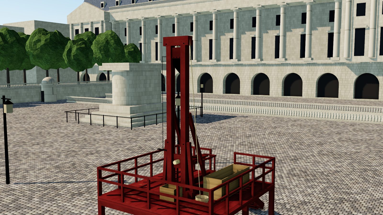
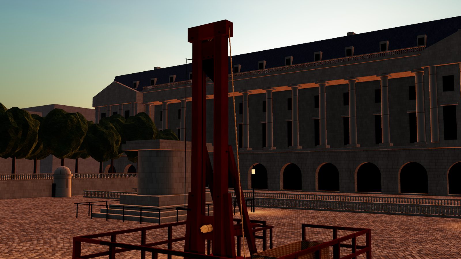
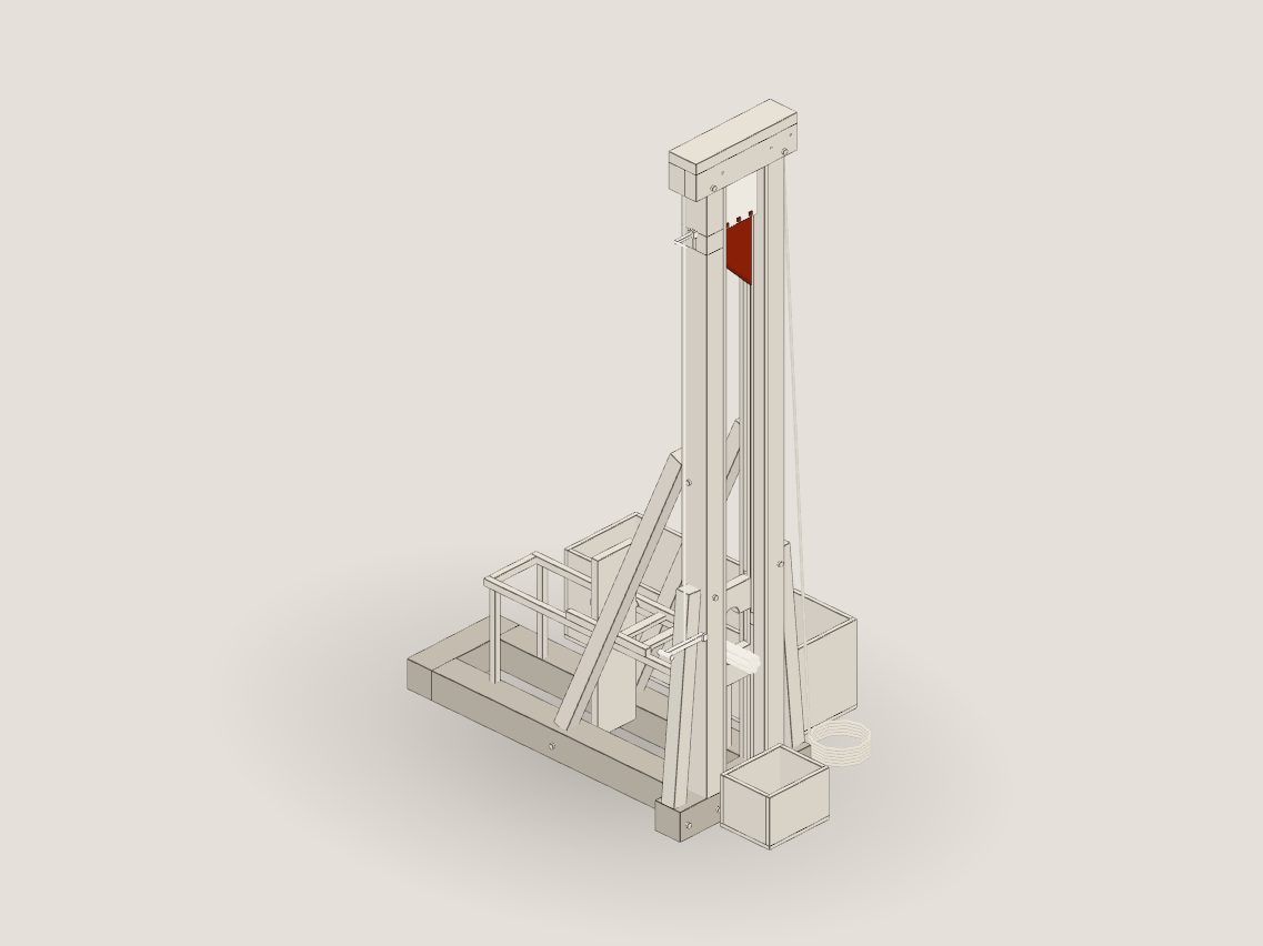
Our 3D reconstruction of the 1793 guillotine, painted ox-blood red on its scaffold in a Paris square.

The episode, chapter by chapter

In March 1792 a surgeon wrote to a carpenter with a list of dimensions, and almost every line in that letter is an engineering decision. Each chapter here follows one in the video: jump to the part you came for, or back into the video at that point. Every claim is tagged with its source, like this: S03. Metres first, the 1792 French units in brackets.

  1. Chapter I1:21

    Why it was made

    A brief written for a machine: no human skill in the loop.

  2. Chapter II3:13

    The Build

    Two posts, a weight, a blade and a rope, from Louis's numbers.

  3. Chapter III5:40

    How It Works

    One cycle, the physics of the drop, and a calculator.

  4. Chapter IV7:07

    Design Choices

    Why fourteen feet, why the slant, why grooves.

  5. Chapter V9:01

    What Went Wrong

    A snag list, swollen grooves, and the fixes.

  6. Chapter VI10:24

    What it did

    The numbers, and who they were.

  7. Chapter VII11:39

    The Leaderboard

    Four scores out of ten. The first entry on the board.

The model
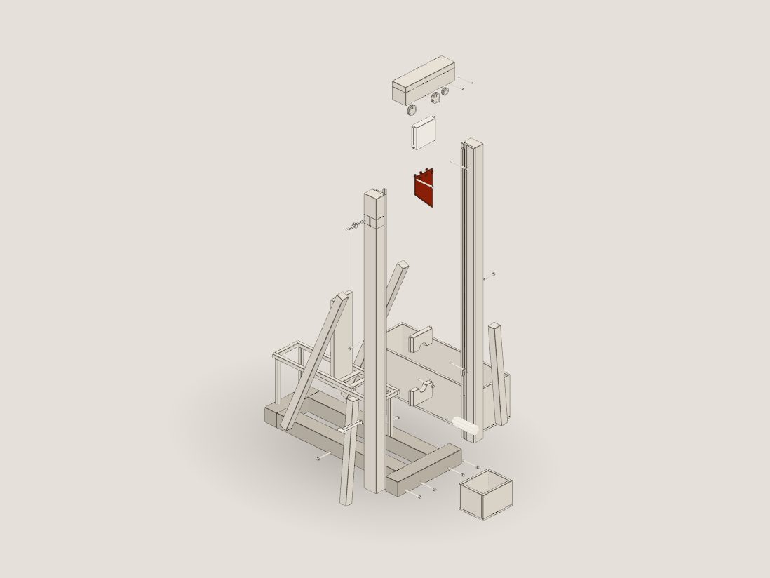
The 3D model of the guillotine in the plain studio look, seen from above at three-quarters.

As promised in the video

Take it apart yourself

This is the model we built the episode with: twenty-one parts, every size from the 1792 paperwork. Spin it, drop the blade in slow motion, or watch all seventeen assemblies come off one by one.

Drop the blade Take it apart

Reconstruction from the 1792 specification; dimensions in metres are model values. Speeds ignore friction. The full model runs best on a laptop or desktop; phones get a lighter version.

Every part is tagged by how sure we are: attested reconstructed assumed illustrative. Turn on "Evidence colours" in the full model to see them.

Chapter I

Why it was made

A brief written for a machine

In eighteenth-century France, even your execution depended on your class: nobles got the sword, commoners the rope. And a sword is only as good as the arm swinging it. In 1766 the Comte de Lally needed several blows. S01

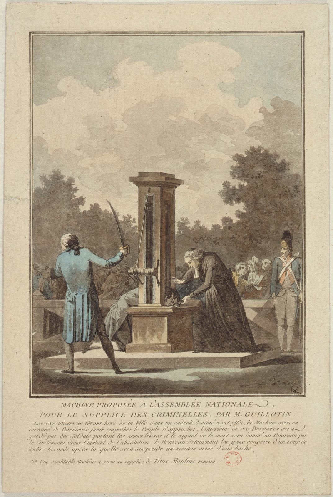
  • 1789: Dr Joseph-Ignace Guillotin proposes one method for everyone, carried out "by means of a simple mechanism". He didn't design it and he didn't build it, but his name stuck. S11 S17
  • 7 March 1792: the surgeon Antoine Louis writes the real design brief. The result must never depend on a person whose "strength and skill can vary"; it has to rely on "invariable mechanical means". That's an engineering requirement, and it explains almost everything in the machine. S01
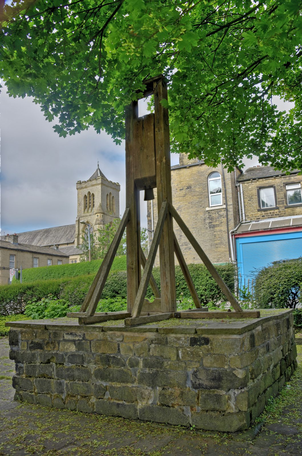
  • The idea was old. By the 1500s Halifax in England had a beheading machine: a heavy block with an axe head, sliding down grooves between two posts, released by pulling a pin. Edinburgh built its own, the Maiden, in 1564. Louis's report points to the English practice. S01 S13 S14
  • April 1792: the job goes to a German harpsichord maker, Tobias Schmidt, who quotes 824 livres against the official carpenter's 5,660, a seventh of the price. He tests it on straw bales, then sheep, then at the Bicêtre hospital on 17 April. Eight days later it is used for real. S04 S06 S07 S25

The three people behind it

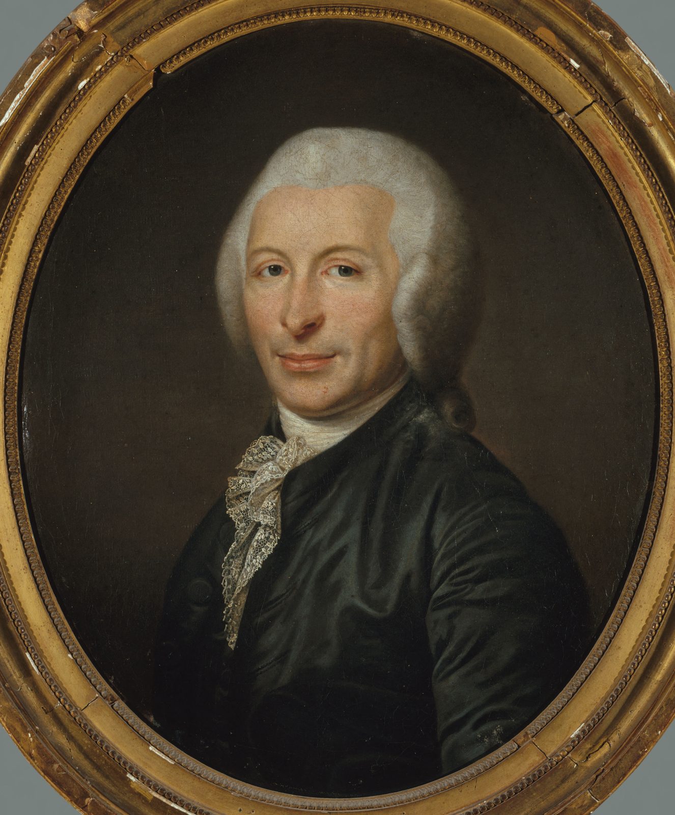
Portrait of Joseph-Ignace Guillotin, an older man in a dark coat and powdered wig.
Unknown artist · Public domain · Wikimedia Commons

Proposed it

Joseph-Ignace Guillotin

Doctor and deputy. Asked for one method for all classes.

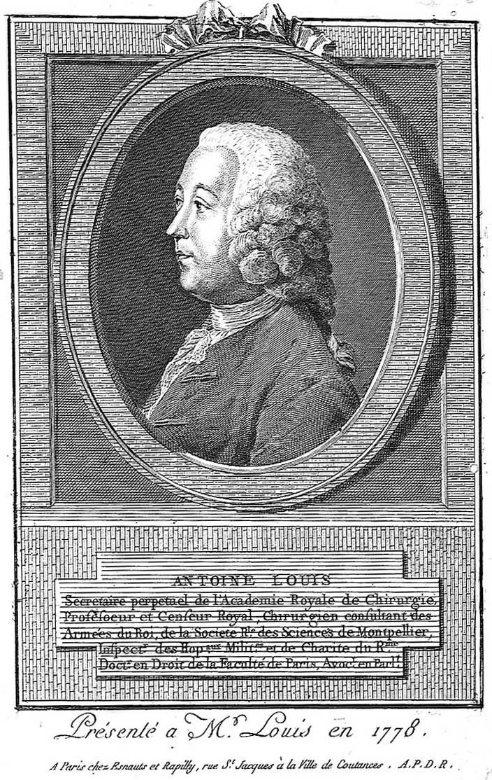
Engraved portrait of the surgeon Antoine Louis in profile, in an oval frame.
Nicolas Dupin, after himself · Public domain · Wikimedia Commons

Specified it

Antoine Louis

Surgeon. Wrote the requirement and the dimensions. It was briefly called the Louisette.

Painting: Schmidt's workshop, with a harpsichord, straw bales and a tall shape under a sheet.AI-generated

Built it

Tobias Schmidt

Harpsichord maker. No portrait of him is known, so this one is painted.

A full-size replica of the Halifax Gibbet: a tall timber frame on a stone plinth, with a blade block at the top.
The Halifax Gibbet (a replica on the original site). Same idea: a weighted blade in grooves between two posts. August Schwerdfeger · CC BY 4.0 · Wikimedia Commons
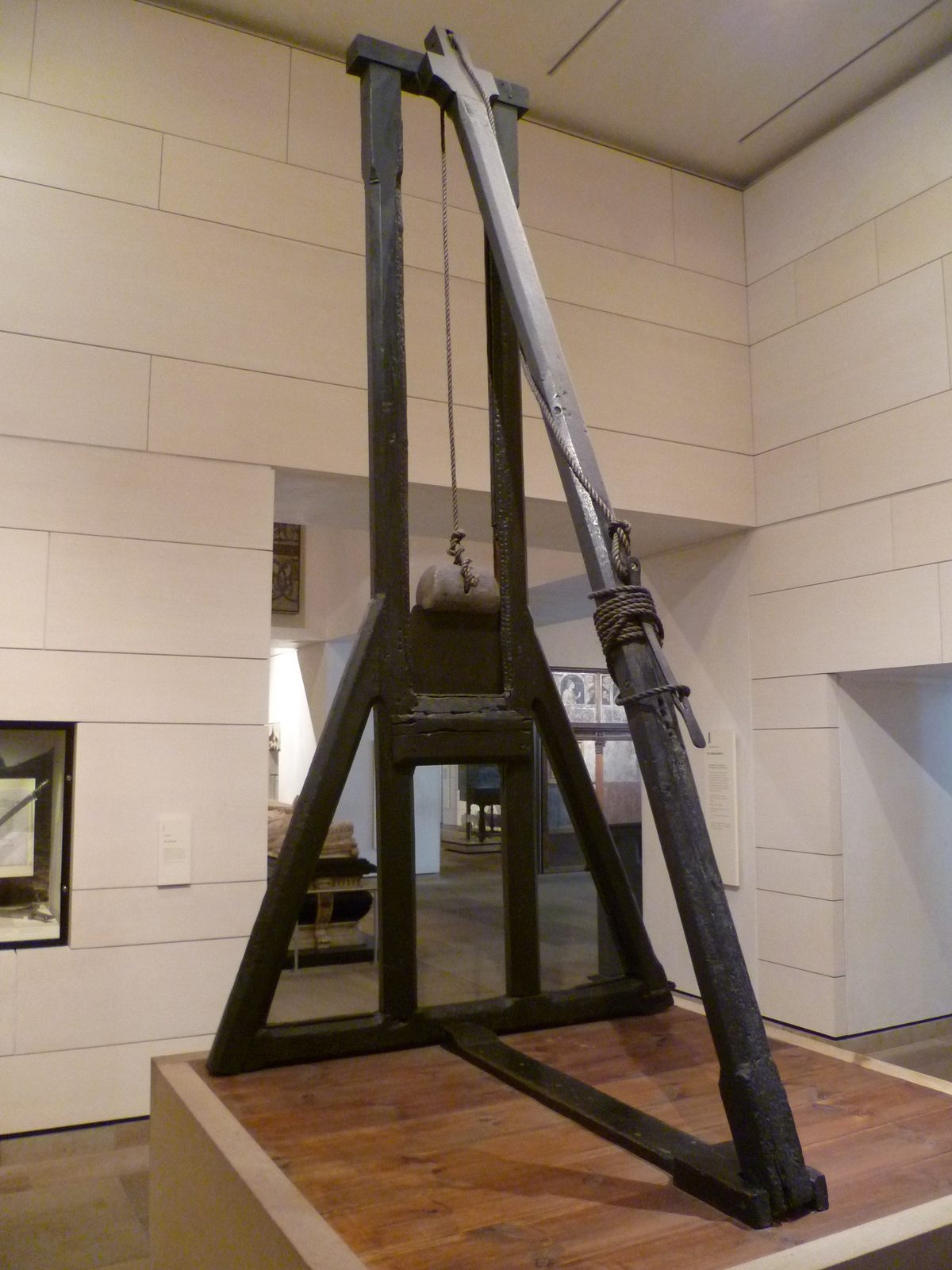
The Maiden, a dark timber beheading frame of 1564, in a museum gallery.
The Maiden, Edinburgh, 1564, now in the National Museum of Scotland. Kim Traynor · CC BY-SA 3.0 · Wikimedia Commons

Chapter II

The Build

Two posts, a weight, a blade and a rope

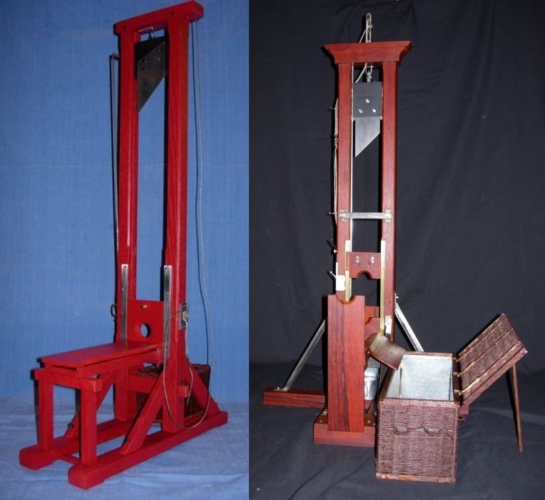
Louis's letter to the carpenter survives, so we can build it from his own numbers. A machine of roughly that age survives too, in a museum in Venlo, in the Netherlands. S03 S27

Uprights
Two oak posts, 16 cm thick (6 pouces) and exactly 32.5 cm apart (1 pied), braced at the sides and back to keep them dead vertical. S03
Grooves
A square groove 2.7 cm deep (1 pouce) down the inside of each post. Remember it: it's the most important feature on the machine, and it causes trouble later. S03
Height
Louis's draft said 3.25 m (10 pieds). The machine as built stood 4.55 m (14 pieds), "for the efficacy of the fall". S03 S05
Weight
The mouton, French for "sheep" and the name of a pile driver's ram: an oak block weighted with metal, riding the grooves on two small lugs, with a steel bar underneath to take the impact. With its blade, about 40 kg. S01 S27
Blade
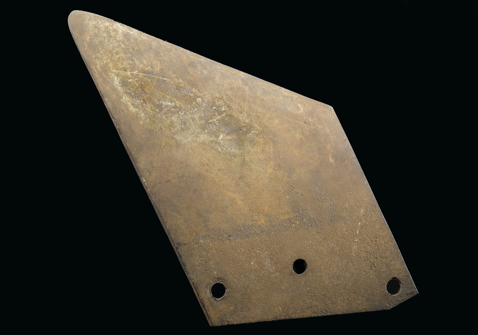
A trapezoid of tempered steel, 30 cm wide, its edge at 45°, held on with three bolts. S07
Hoist
A rope from a ring on top of the weight, over a pulley at the top of each post, and down the outside. S03
Release
A rocker arm through one post hooks under the weight; a rod links it to a handle lower down the same post. S27 S28
Restraint
The lunette ("little moon"): two boards with half-circles cut out, the upper one sliding down to close. Behind it, the bascule, a tilting plank with straps. S02 S08

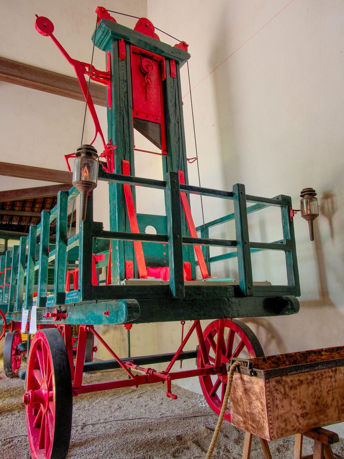
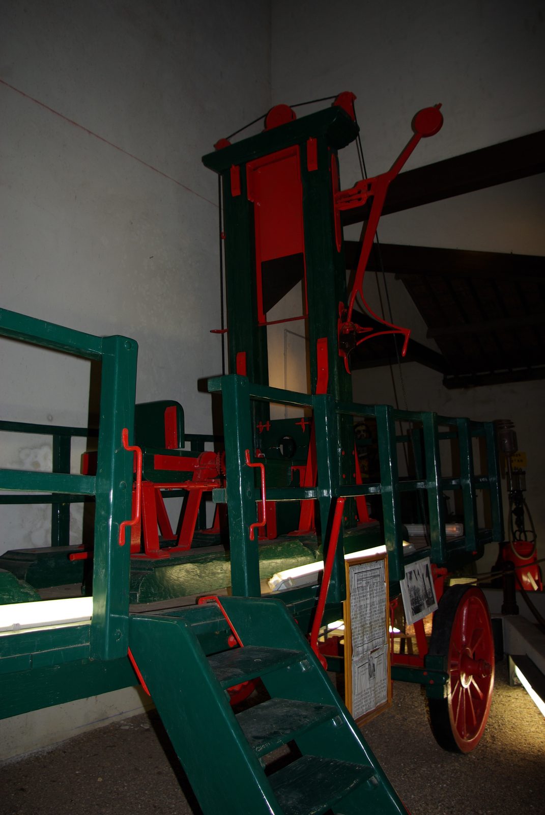
And the whole thing is a kit. The joints are mortise and tenon, locked with removable pins, so it can be knocked down, loaded onto a wagon and rebuilt somewhere else. The carpenter's first quote even included horses and wagons to set it up and take it down for every execution. S04 S27

All 21 parts, with sizes and how sure we are
IDPartSize in the modelEvidence
P01Scaffold deck, railing and 10-step stair4.0 × 3.8 m, 2.0 m highreconstructed
P02Sole (base frame)sills 0.20 × 0.20 m; 1.10 × 2.40 mattested
P03Uprights (2)0.162 × 0.20 × 4.1 m; gap 0.325 mattested
P04Grooves with copper linerssquare, 0.027 m deepattested
P05Crossbeam (chapeau)0.85 × 0.25 × 0.22 mattested
P06Pulleys (2 + outer pulley)≈0.12 m; outer ≈0.08 mattested
P07Side and rear braces (4)0.10 × 0.10 mattested
P08Mouton with lugs, ring and crash bar0.32 × 0.30 × 0.08 mreconstructed
P09Blade (couperet) + 3 bolts0.30 m wide; edge 45°reconstructed
P10Hoisting rope≈0.02 m hemp, two fallsreconstructed
P11Rocker-arm release, rod and handlepivot ≈4.0 m; handle ≈1.3 mreconstructed
P12Lunette, lower half0.365 × 0.20 × 0.06 m; hole 0.13 mreconstructed
P13Lunette, upper halfas P12; slides in its own groovesreconstructed
P14Bascule (tilting plank) with 2 straps1.2 × 0.32 × 0.05 mattested
P15Bascule table and carriagetop at 0.875 m; 1.7 m longreconstructed
P16End of the grooves (impact point)stops, top at 1.22 mreconstructed
P17Head basket≈0.5 × 0.4 × 0.35 millustrative
P18Body basket≈1.8 × 0.6 × 0.6 millustrative
P19Paintox-blood redattested
P20Straw bundle (demonstration target)≈0.12 m bundleillustrative
P21Joint pins (mortise-and-tenon locks)iron pins at each frame jointreconstructed
attested: stated in a 1792 sourcereconstructed: inferred from sourcesassumed: modelling assumptionillustrative: picture only
An old trapezoid guillotine blade with three bolt holes, on a black background.
A blade of the period, with its three bolt holes. Wellcome Collection · CC BY 4.0 · Wikimedia Commons
A travelling guillotine of 1794 laid on a green and red cart, in a museum.
The kit, for real: a travelling guillotine of 1794 on its cart, Musée Maurice Dufresne. Alf van Beem · Public domain · Wikimedia Commons
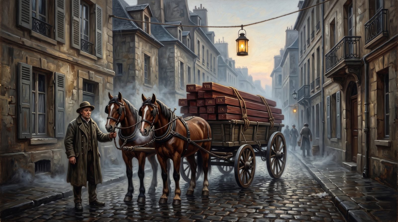
Painting: the numbered timbers of the machine on a wagon in a Paris street at dawn.AI-generated
Knocked down and loaded for the next town.

Chapter III

How It Works

One cycle, from the bascule to the reset

Gravity does the cutting. The engineering is in holding forty kilograms four metres up, putting the target in exactly the same place every time, and letting go cleanly.

  1. The bascule tips forward and slides, bringing the neck into exactly the same spot every time. S08
  2. The upper lunette drops and locks it in place.
  3. The executioner lifts the release handle, the rocker arm lets go, and gravity takes over. S06 S28
  4. The blade falls about 2.5 m in roughly 0.7 s. By the time it reaches the neck it's doing about 7 m/s, or 25 km/h, carrying around a kilojoule. The cut itself takes a couple of hundredths of a second.
  5. The weight hits the end of its grooves and the cycle runs in reverse. An assistant hauls on the rope, and because it runs through a ring on the weight, each end carries only half the load. Up it goes until the rocker arm clicks back into place. S03

E = m·g·h ≈ 40 kg × 9.81 m/s² × 2.51 m ≈ 0.99 kJ
v = √(2gh) ≈ 7.0 m/s (25 km/h)
t = √(2h/g) ≈ 0.72 s

To picture a kilojoule: a 25 kg bag of cement dropped from four metres, all of it focused onto one sharp edge.

In the 1860s an observer timed the whole process, from the first step to the basket lid closing, at fourteen seconds. S08

Chapter IV

Design Choices

Why fourteen feet, why the slant, why grooves

So why is it built like this? Three choices make it work, and every one of them goes back to Louis's brief.

1 · Why fourteen feet?

Louis compared the weight to a pile driver's ram, "whose force increases with the height from which it falls". S01

Double the drop and you double the energy. But the speed only rises by about 40%, and a taller frame is harder to build, keep straight and reset. Fourteen feet was their balance. They didn't calculate it the way we can; they had a rule of thumb, and they tested it. Try doubling it in the calculator.

2 · Why the slanted blade?

Louis's report gives the reason. Under a microscope a cutting edge is just a very fine saw, and a saw cuts by sliding, not pressing. You know this from your kitchen: press a knife straight down on a tomato and it squashes; slide it, and it glides through. S01

Angle the blade at 45° and for every centimetre it falls, it also slides a centimetre sideways. In the ideal case that halves the force needed. And because the edge meets the neck at one point and works across, only a little of it is cutting at any instant. S19

3 · Why grooves, a lunette and a bascule?

Everything is built for repeatability. The grooves make the blade fall in the same line every time; the bascule and lunette put the neck in the same place every time. That was Louis's brief: no human skill in the loop. S01

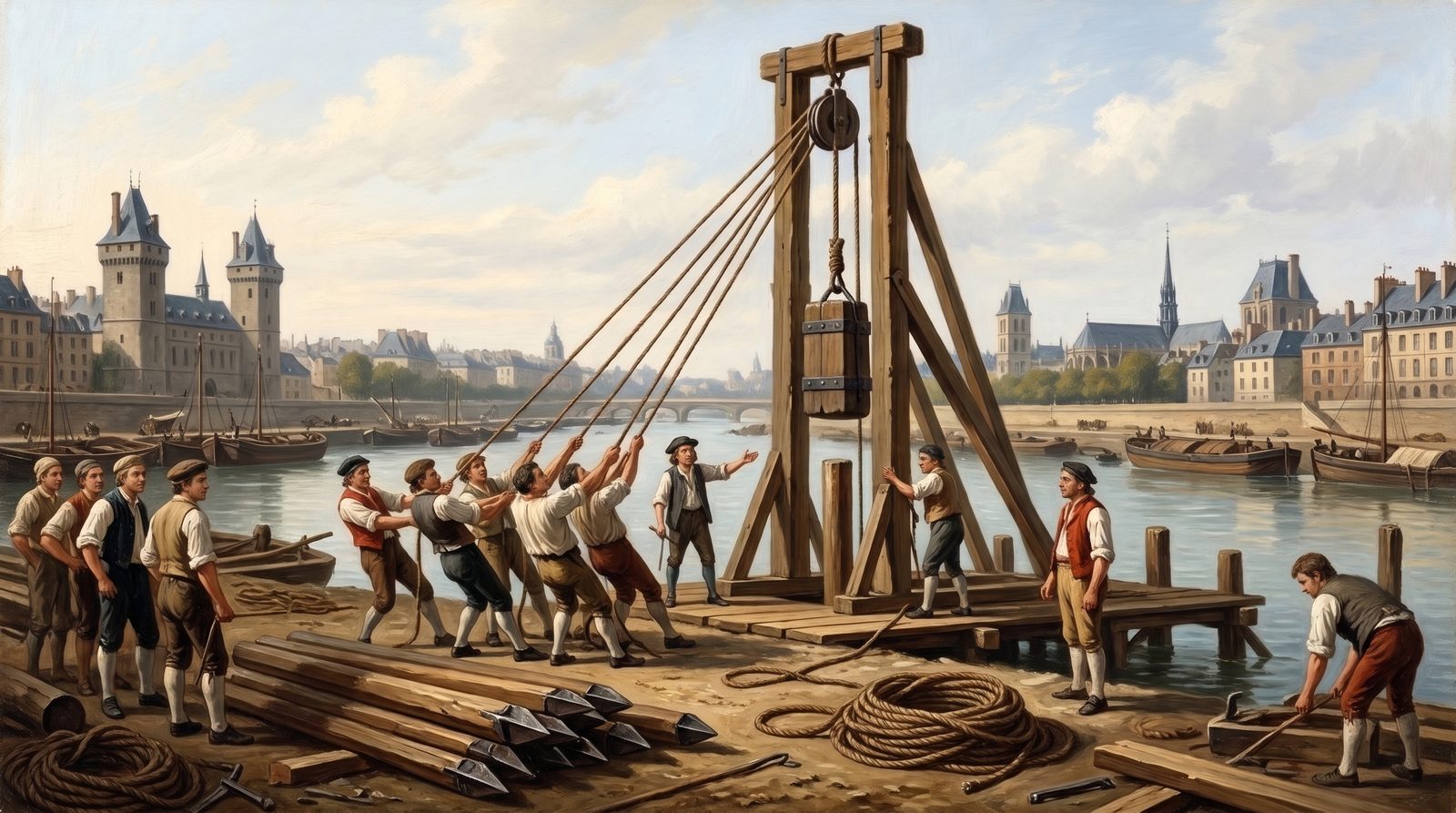
Engraving: a pile driver and its ram, with the ram's fall drawn in.AI-generated
"Whose force increases with the height from which it falls."
Engraving: a knife pressing on a tomato against a knife slicing through one, with a 45-degree triangle.AI-generated
Press and it squashes; slide and it cuts.

Chapter V

What Went Wrong

A snag list, swollen grooves and the fixes

No machine works perfectly the first time, and this one had problems fast. In June 1792 an architect, Giraud, inspected the first machine, called it "made in haste", and wrote a snag list that reads like an engineer's. S07

  • Line the wooden grooves with copper.
  • Swap the wooden fittings for iron.
  • Bolt the rope hooks, which were only nailed on.
  • Keep two spare blades ready.

That groove

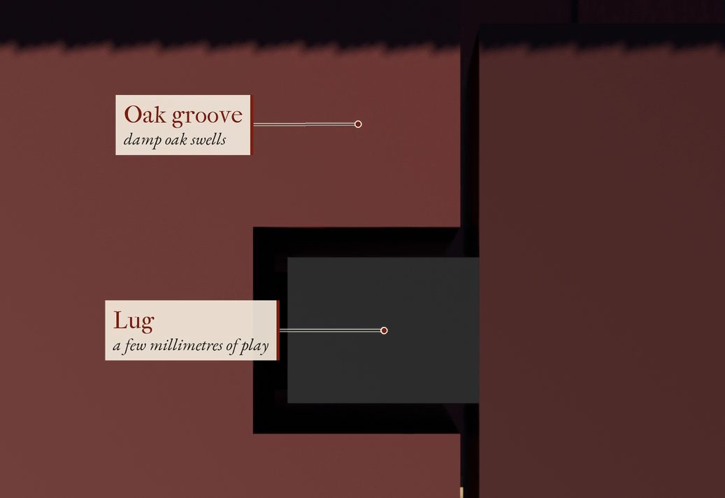
Built to Louis's numbers, the lugs have only a few millimetres of play, and damp oak swells: just 1% on a 16 cm post is 1.6 mm (our model's estimate). In July 1792 the grooves swelled and the blade failed to cut all the way through. Metal doesn't swell, so metal-lined grooves became mandatory. S07 S28

The rope and the stop

On the earliest machines the rope stayed tied to the weight and fell with it. When it snagged, executions went badly wrong. And the energy left over hit the bottom of the grooves with something like twenty tonnes of force for an instant (about 200 kN if it stops within 5 mm; an illustration, not a measurement). Again and again it knocked the frame out of line. By the 1860s the weight landed on springs topped with rubber. S08 S27

Around 1870 France rolled every fix into one national design, the Berger model, and that's the guillotine it used until 1977. S09 S10

3D still, labelled: a lug riding in its oak groove, with a few millimetres of play; damp oak swells.
Painting: rain running off stacked oak beams in a Paris timber yard.AI-generated

Chapter VI

What it did

The numbers, and who they were

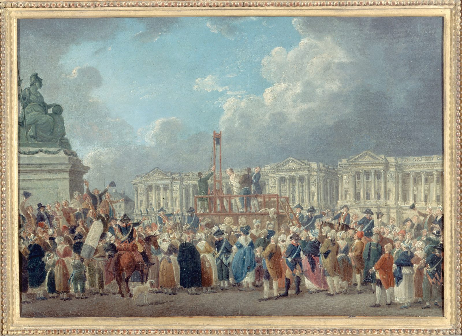
It did its job with terrible efficiency. On 31 October 1793 the Paris executioner and his team executed twenty-one deputies in thirty-six minutes. S15

During the Reign of Terror, 16,594 official death sentences were carried out across France in just over a year, most of them by guillotine. It took a king, a queen, the chemist Lavoisier and, in the end, the revolutionaries who had used it, Robespierre included. S11 S12 S15

About eight in ten of those people weren't nobles at all. They were craftsmen, farmers, ordinary people.Of those condemned, 31% were artisans and 28% peasants S29

A machine designed to make death equal also made it fast, cheap and easy to repeat. France kept using it until 1977, and abolished the death penalty four years later. S11

Chapter VII

The Leaderboard

Four scores out of ten

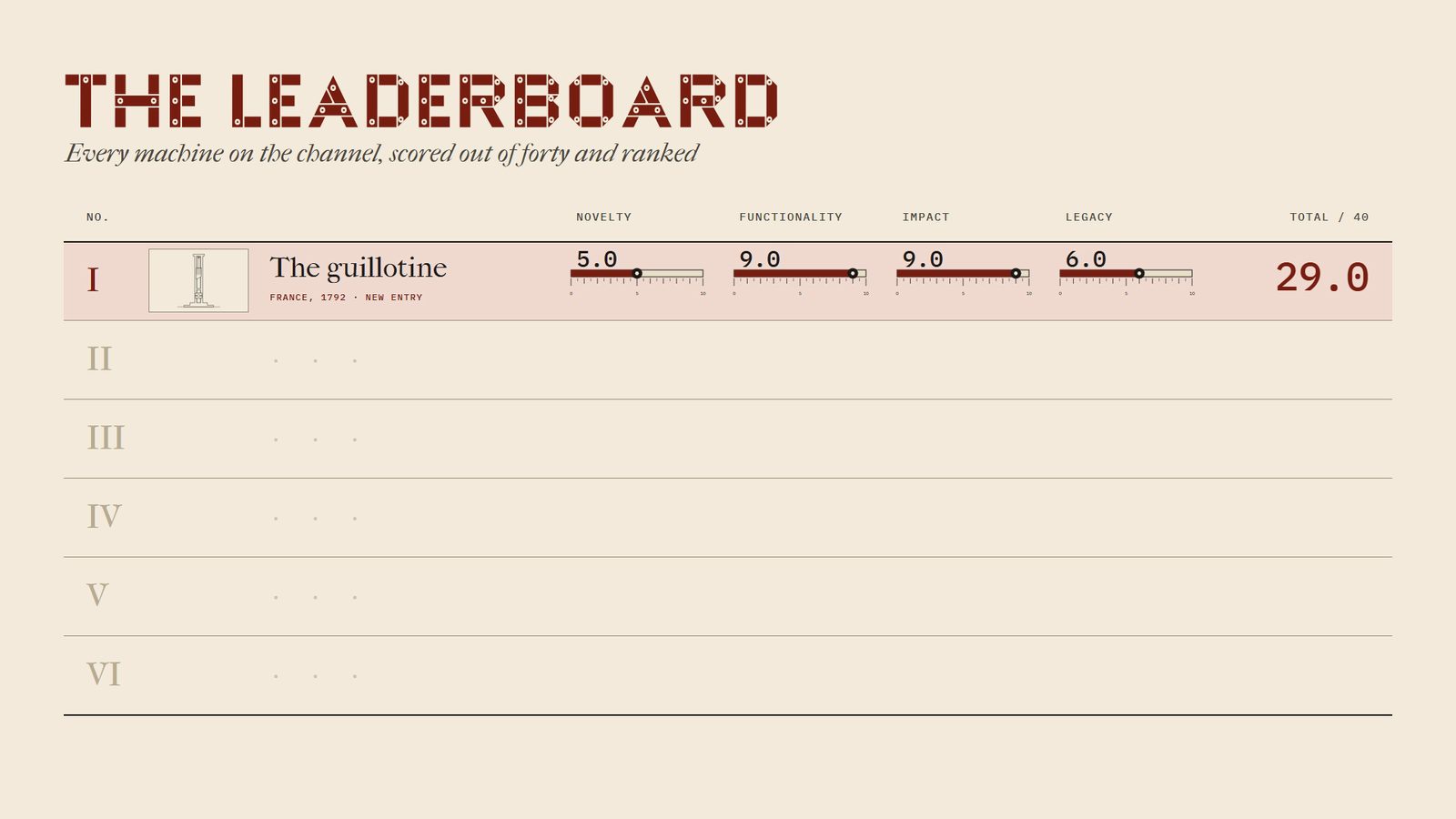
Every machine on this channel gets four scores out of ten: how new the engineering was for its time, how well it did its job, how much it changed its world, and how much of its engineering lives on.

It's the first entry on the board, so for now it's in first place, and last place. Which machine should challenge it next? Tell us in the video's comments.

▶ Suggest the next machine

RankDrawingMachineNoveltyFunctionalityImpactLegacyTotal/40
IThe guillotineFrance, 1792 · new entryNovelty5.0Functionality9.0Impact9.0Legacy6.029.0

Ranked by total · ties share a place · the rulers run 0 to 10 in half-point steps

Novelty 5.0
The grooves, the weight and the pin were centuries old. New: the slanted cut, the bascule and lunette as one system, and a national standard built from written specifications.
Functionality 9.0
Fast, repeatable, no skill required. Minus a point for the early teething problems.
Impact 9.0
It became the face of the Revolution and stayed in use for nearly two centuries.
Legacy 6.0
Its job is, thankfully, obsolete. Its geometry lives on in paper cutters and metal shears that angle their blades for the same reason. S22 S23

See a real one

A few machines and their ancestors survive in museums. Displays change, so check before you travel.

  • A travelling guillotine on its cart in a museum.
    Duch.seb · CC BY-SA 3.0 · Wikimedia Commons

    Azay-le-Rideau, France

    Musée Maurice Dufresne

    A travelling guillotine of 1794, on its cart.

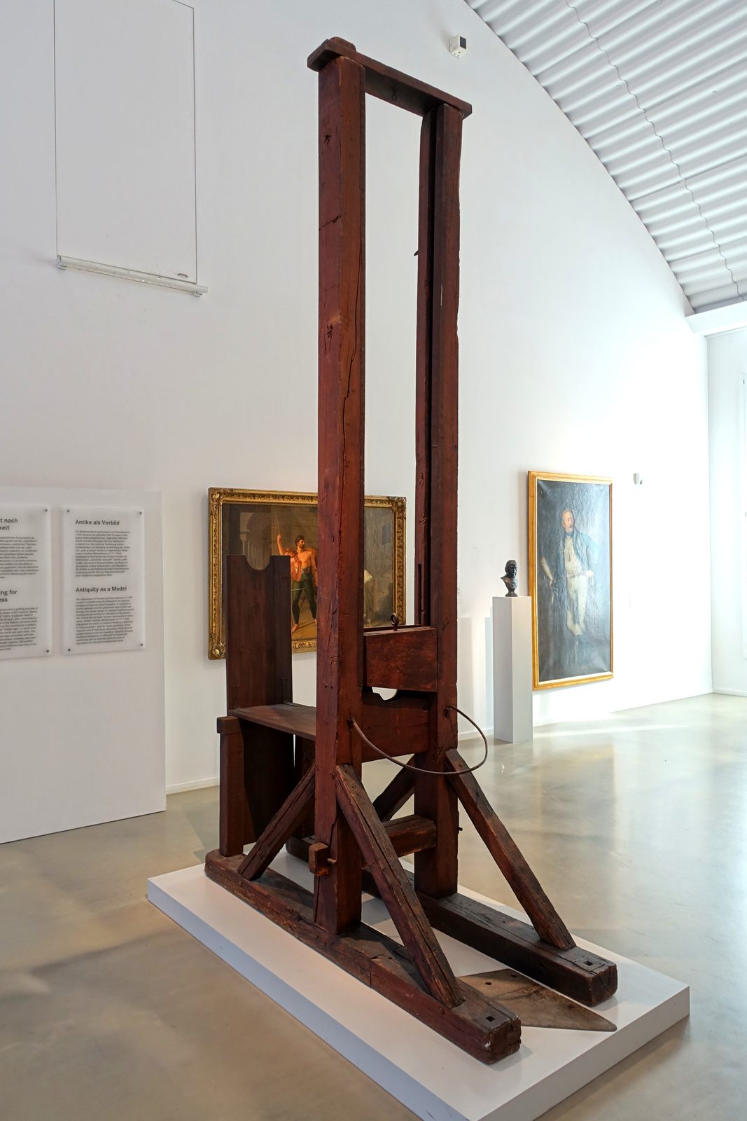
  • The Dillenburg guillotine frame in a museum gallery.
    Daderot · Public domain · Wikimedia Commons

    Nuremberg, Germany

    Germanisches Nationalmuseum

    The Dillenburg machine, used until 1813: the wooden frame and its grooves.

  • The Maiden in the National Museum of Scotland.
    Kim Traynor · CC BY-SA 3.0 · Wikimedia Commons

    Edinburgh, Scotland

    National Museum of Scotland

    The Maiden of 1564, the ancestor from chapter I.
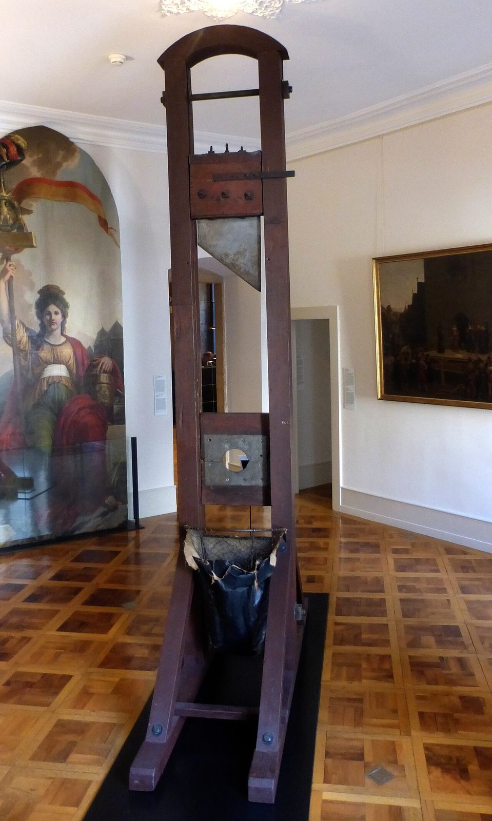
  • The Geneva guillotine standing in a panelled museum room.
    MHM55 · CC BY-SA 4.0 · Wikimedia Commons

    Geneva, Switzerland

    Maison Tavel

    The Geneva guillotine; its frame was restored in the early 20th century.

  • Venlo, Netherlands

    Limburgs Museum

    A machine of about 1792, roughly the age of the one we rebuilt. S27

  • Marseille, France

    MuCEM

    A Berger guillotine of 1872, rarely shown; it was displayed in October 2025. S24

Sources and credits

The primary sources are Antoine Louis's own letters of 1792, transcribed in Hector Fleischmann's La Guillotine en 1793 (1908). Where sources disagree, the video and this page say so.

Sources

  1. S01Antoine Louis, Consultation motivée sur le mode de décollation, 7 March 1792. In H. Fleischmann, La Guillotine en 1793 (1908), ch. IV, French Wikisource.
  2. S02Louis to Roederer, 24 March 1792 (Schmidt's design: "oblique cut"). Same chapter as S01.
  3. S03Louis, instructions to the carpenter Guidon, 30 March 1792 (the dimensions). Same chapter.
  4. S04Louis to Roederer, 1 April 1792 (Guidon's 5,660-livre quote; horses and wagons). Same chapter.
  5. S05Louis to Cullerier, 12 April 1792 ("fourteen feet… for the efficacy of the fall"). Same chapter.
  6. S06Louis to Roederer, 19 April 1792 (the Bicêtre trial; "push the lever"). Same chapter.
  7. S07French Wikipedia, "Guillotine": the builders, Giraud's inspection, the authorship of the blade.
  8. S08Maxime Du Camp, Paris, ses organes, ses fonctions et sa vie, ch. XVI ("La Place de la Roquette"), on French Wikisource: the 1860s machine, measured and timed.
  9. S09French Wikipedia, "Guillotine": later forms, assembly, incidents, museums.
  10. S10German Wikipedia, "Guillotine": the 1792 and Berger models.
  11. S11English Wikipedia, "Guillotine".
  12. S12English Wikipedia, "Reign of Terror" (16,594 death sentences).
  13. S13English Wikipedia, "Halifax Gibbet".
  14. S14English Wikipedia, "Maiden (beheading)".
  15. S15English Wikipedia, "Charles-Henri Sanson" (21 deputies in 36 minutes).
  16. S16English Wikipedia, "Johann Reichhart".
  17. S17English Wikipedia, "Joseph-Ignace Guillotin".
  18. S18Evan Andrews, "8 Things You May Not Know About the Guillotine", HISTORY (2014, updated 2025).
  19. S19A. G. Atkins (2016), "Slice–push, formation of grooves and the scale effect in cutting", Interface Focus 6: 20160019.
  20. S20English Wikipedia, "Martyrs of Compiègne".
  21. S21English Wikipedia, "Dialogues of the Carmelites".
  22. S22English Wikipedia, "Paper cutter"; French Wikipedia, "Massicot".
  23. S23English Wikipedia, "Shear (sheet metal)".
  24. S24Connexion France, "1872 guillotine on public display at French museum" (29 October 2025).
  25. S25English Wikipedia, "Nicolas Jacques Pelletier".
  26. S26b"Shearing of sheet metal with angled tools", Int. J. Mechanical and Materials Engineering (2016).
  27. S27boisdejustice.com, "1792 Guillotine Models": a replica builder's research on the 1792 type and the Venlo machine.
  28. S28guillotine.dk, "1792 guillotine explained": the rocker-arm release.
  29. S29French Wikipedia, "Terreur (Révolution française)": who the victims were.

Pictures

Archive pictures come from Wikimedia Commons; each links to its file page and licence.

  • S0-01 Louis's design, from Fleischmann's La Guillotine en 1793, 1908. Hector Fleischman · Public domain · Wikimedia Commons
  • S2-01 Machine proposée à l'Assemblée nationale (c. 1791). Jean-François Janinet · Public domain · Wikimedia Commons
  • S2-02 Portrait of Joseph-Ignace Guillotin, Musée Carnavalet. Unknown artist · Public domain · Wikimedia Commons
  • S2-03 Antoine Louis, 1778. Nicolas Dupin, after himself · Public domain · Wikimedia Commons
  • S2-04 Halifax Gibbet (replica), 2016. August Schwerdfeger · CC BY 4.0 · Wikimedia Commons
  • S2-06 The Maiden, National Museum of Scotland. Kim Traynor · CC BY-SA 3.0 · Wikimedia Commons
  • S3-02 Travelling guillotine of 1794, Musée Maurice Dufresne. Alf van Beem · Public domain · Wikimedia Commons
  • S3-03 Travelling guillotine, Musée Maurice Dufresne. Duch.seb · CC BY-SA 3.0 · Wikimedia Commons
  • S3-04 Dillenburg guillotine (used until 1813), Germanisches Nationalmuseum. Daderot · Public domain · Wikimedia Commons
  • S3-06 Guillotine blade, France. Wellcome Collection · CC BY 4.0 · Wikimedia Commons
  • S3-08 Models of the 1792 and 1872 guillotines. Michael / boisdejustice.com · used with credit · Wikimedia Commons
  • S5-03 Louis XVI in coronation robes. Antoine-François Callet · Public domain · Wikimedia Commons
  • S6-03 Berger's scale model of the guillotine, Paris Musées. Alphonse Léon Berger · CC0 · Wikimedia Commons
  • S7-01 Une exécution capitale, place de la Révolution, Musée Carnavalet, 1793. Pierre-Antoine Demachy · Public domain · Wikimedia Commons
  • S7-06 Marie-Antoinette with a rose, 1783. Élisabeth Louise Vigée Le Brun · Public domain · Wikimedia Commons
  • S7-07 Antoine-Laurent Lavoisier and his wife, The Met, 1788. Jacques-Louis David · CC0 · Wikimedia Commons
  • S7-08 Portrait of Robespierre, Musée Carnavalet. Unknown artist · CC0 · Wikimedia Commons
  • S7-21 The Geneva guillotine, Maison Tavel. MHM55 · CC BY-SA 4.0 · Wikimedia Commons

Illustrations

The paintings and engravings marked "AI-generated illustration" were made with Google's Nano Banana and Veo, in the style of period history painting and the Encyclopédie. They show the world around the machine, never the machine itself; the guillotine you see is always our 3D model. Only public-domain art was used as a reference.

The 3D model

A reconstruction of the Paris machine of 1793 from Antoine Louis's 1792 specification, with gaps filled from Du Camp's 1860s measurements and replica research. Dimensions in metres are model values; speeds ignore friction; the square around it is illustrative, not a survey. Built with three.js (MIT); the light viewer is Google's model-viewer (Apache 2.0).

Type

EB Garamond, IM Fell French Canon and IBM Plex Mono, under the SIL Open Font Licence, served from this site. Licence files.